|
Main Body: |
Forging Brass In Chrome Plated |
Brackets: |
Steel |
|---|---|---|---|
|
Max. Working Pressure: |
6 Bar |
Working Temp Range: |
5 - 60 ℃ |
|
Flow Meter Scale: |
0 - 5 L/Min (±10%) |
Main Connection: |
1'' F |
|
Outlets: |
3/4'' M |
Central Distance: |
50 Mm |
|
Ways Available: |
2 -12 Ways |
||
|
Highlight: |
Pre-Assembled Water Distribution Manifolds, Pre-Assembled Water Distribution Manifolds |
||
The distribution manifold for radiant panel systems is used to optimally distribute the thermal medium in underfloor heating system circuits, in order to improve the control of the panel thermal emission.
This series of manifolds is composed of:
- return manifold with built-in shut-off valves fitted for thermostatic actuator;
- flow manifold complete with flow meters with 0~5 l/m scale and flow rate balancing valves;
- end fittings with automtic air vent and drain cock;
- steel mounting brackets for use with box or for direct wall mounting.
In order to determine the hydraulic characteristics of the circuit, it is necessary to calculate the total head loss suffered by the flow rate of medium on passing through the devices forming the manifold assembly and the radiant panel circuits. From a hydraulic point of view, the system consisting of the manifold assembly and the circuits can be represented as a set of hydraulic elements arranged in series and in parallel.

When the hydraulic characteristics of each component and the design flow rates are known, the total loss can be calculated as the sum of the partial head losses for each specific component in the system, as indicated by the formula:
△pTot. = △pRV +△pLoop + △pSV + △pManif. F + △pManif. R
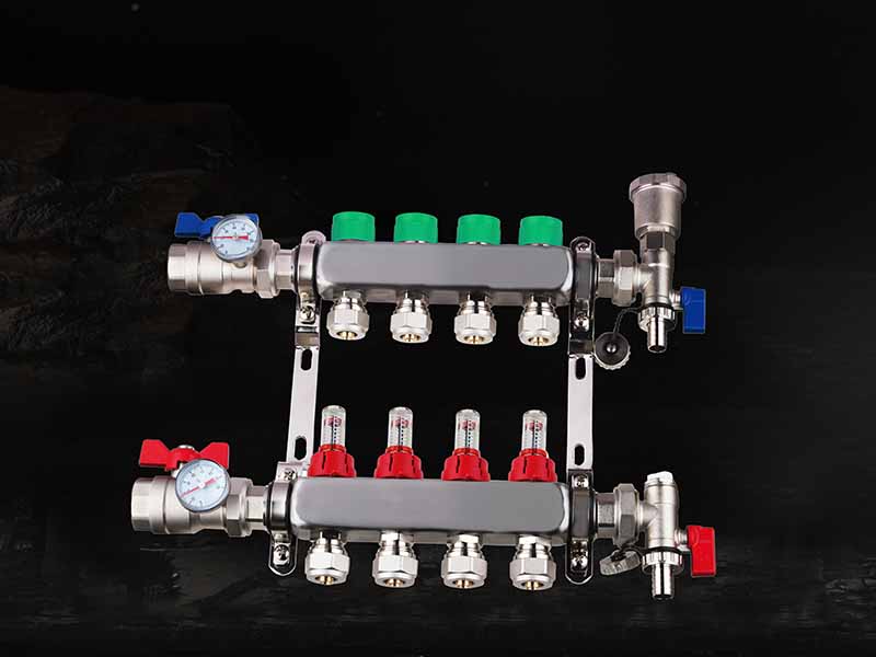
Manifold Series
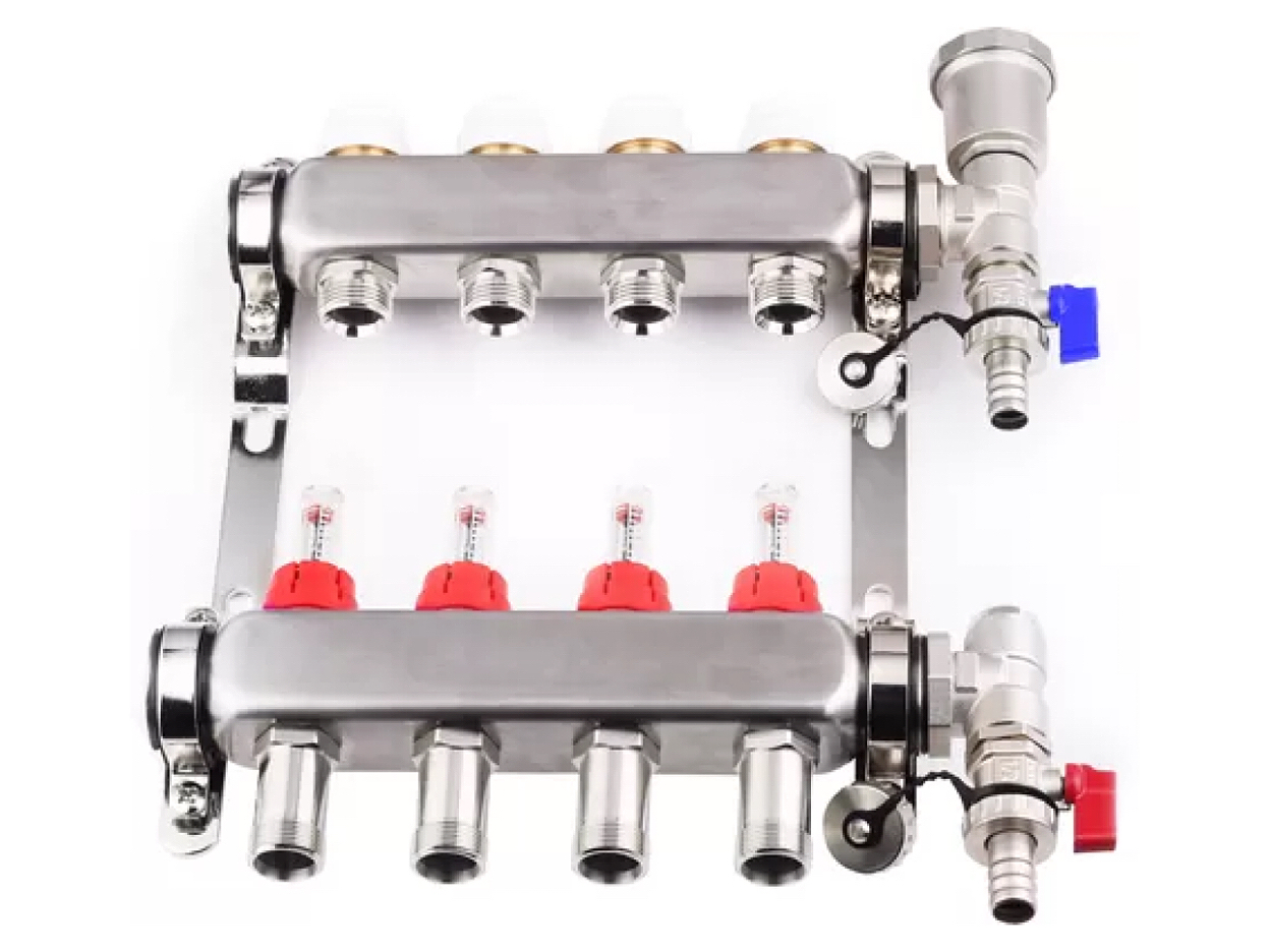
XAJ732 Brass Manifold